Welding on bridges is more than a construction step. It helps determine whether the bridge deck performs as one integrated structural system or as two separate materials. In fact, a properly executed composite bridge deck system can carry 30 to 50 percent more load than the same steel beam supporting a non-composite concrete slab. As a result, stud welding creates the composite action required for modern bridge construction. Northland Fastening Systems supplies the stud welding products that make this critical connection possible on bridge programs across the country. As a result, stud welding creates that composite action — and without it, modern bridge construction as we know it would not exist. Northland Fastening Systems supplies the stud welding products that make this critical connection possible on bridge programs across the country.
What Composite Action Actually Means in Bridge Construction
Structural engineers design bridge decks as composite systems because the combination of steel and concrete outperforms either material working independently. Steel carries tension loads exceptionally well. Meanwhile, concrete carries compression loads efficiently. As a result, when the two materials work together as one unit, each handles the forces it is best suited for — and the overall system becomes significantly stronger and stiffer than its individual parts.
However, the critical challenge is making steel and concrete act together structurally. Left on their own, a steel beam and a concrete slab simply deflect independently under load. The slab slides relative to the beam at their interface, which eliminates the composite benefit entirely. Consequently, engineers specify shear connectors — large-diameter stud welds attached to the top flange of the steel beam — to lock the two materials together and force them to deflect as one unit.
This horizontal shear transfer is the mechanical foundation of every composite bridge deck built in the United States today.
The Role of Stud Welding in Creating the Composite Connection
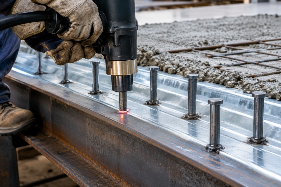
Welding on bridges using the drawn arc stud welding process delivers the shear connector installation that composite design requires. Then, each shear connector welds to the top flange of the steel beam in under one second. After the concrete deck pours and cures around the connectors, the mechanical interlock between the studs and the hardened concrete locks the two materials together permanently.
Additionally, the drawn arc process suits this application specifically because it produces a full cross-sectional weld that meets the structural strength requirements AWS D1.5 — the Bridge Welding Code — mandates for composite construction. Furthermore, drawn arc welding completes each weld at the speed production bridge fabrication demands. A fabricator installing hundreds of shear connectors across a series of beams needs a process that is both fast and consistently reliable — and Northland Fastening Systems provides the stud welding products and solutions needed to support this demanding process.
According to AWS D1.5, shear connectors must achieve a minimum tensile strength of 65,000 psi. Every stud used in bridge composite construction must meet this requirement, with material certification documentation available for inspection. Therefore, this makes material sourcing a quality and compliance decision — not simply a price decision.
How Shear Connector Spacing Is Determined
Engineers calculate shear connector spacing based on the magnitude of horizontal shear forces at the steel-concrete interface across each span. The calculation follows AASHTO LRFD Bridge Design Specifications, which governs bridge design in the United States.
For example, the table below shows the general relationship between bridge span length, beam size, and the typical shear connector density engineers specify:
| Bridge Application | Typical Shear Connector Diameter | Typical Spacing Range | Governing Standard |
|---|---|---|---|
| Short span highway bridge (up to 60 ft) | 3/4″ | 6″ to 12″ on center | AASHTO LRFD / AWS D1.5 |
| Medium span highway bridge (60–120 ft) | 3/4″ or 7/8″ | 6″ to 9″ on center | AASHTO LRFD / AWS D1.5 |
| Long span bridge (120 ft+) | 7/8″ | 4″ to 6″ on center | AASHTO LRFD / AWS D1.5 |
| Railroad bridge | 7/8″ | 4″ to 6″ on center | AREMA / AWS D1.5 |
| Pedestrian bridge | 3/4″ | 8″ to 12″ on center | AASHTO / AWS D1.5 |
Closer spacing increases the number of shear connectors per beam and therefore the degree of composite action achieved. Full composite design uses the maximum number of connectors that the interface shear calculation requires. By comparison, partial composite design uses fewer connectors — typically 50 to 75 percent of full composite — to reduce cost while still achieving a defined level of composite benefit.
Thru-Deck Welding: The Standard Method on Most Bridge Programs
Most modern bridge deck construction uses steel decking as the formwork for the concrete pour. In this method, shear connectors weld directly through the galvanized steel decking to the beam flange beneath — a process called thru-deck welding. Furthermore, this method eliminates the need to remove the decking after the pour, since it becomes a permanent component of the composite system.
Additionally, Northland Fastening Systems supplies the correct shear connectors, ceramic ferrules, and weld-thru accessories for thru-deck bridge applications. Thru-deck welding requires specific ferrule types and machine settings that differ from direct-to-flange welding — confirm these requirements with your supplier before placing any order for a thru-deck program.
For fabrication shops and contractors evaluating equipment options for a bridge program, stud welders suited for 3/4″ and 7/8″ shear connector applications must deliver sustained power output at the high duty cycles that large beam fabrication programs demand. Otherwise, a machine that cannot maintain consistent arc parameters across hundreds of welds per shift will produce variable flash rings that fail AWS D1.5 visual inspection criteria.
AWS D1.5 Inspection Requirements for Bridge Shear Connectors
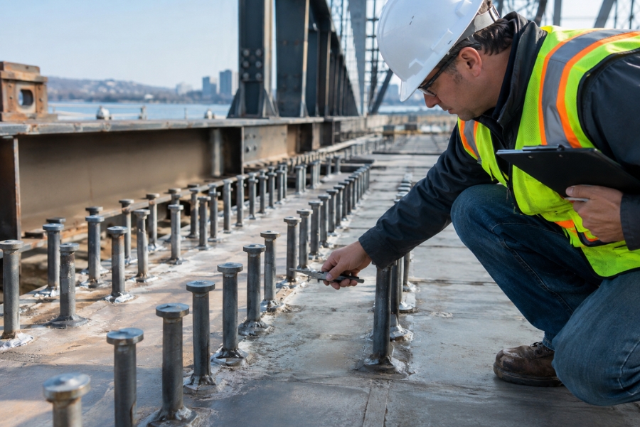
Welding on bridges under AWS D1.5 requires 100 percent visual inspection of every installed shear connector. Each weld must display a complete 360-degree flash ring around the base of the stud. If this happens, any gap in the flash ring triggers the bend test requirement — the stud must be bent 15 degrees in the direction of the missing flash without fracture at the weld zone or heat-affected zone.
If a stud fails the bend test, the procedure must be corrected and two additional test welds completed successfully before production continues. However, failed studs may be repaired with a fillet weld using low-hydrogen electrodes, subject to the engineer’s approval — though many bridge specifications require full removal and replacement rather than repair.
For teams working on large bridge programs, equipment rentals offer a practical solution when the stud welding machine requirement for the program exceeds what a fabrication shop normally keeps on hand. In many cases, renting a machine rated for 7/8″ shear connectors at high duty cycle for the duration of a bridge project is often more cost-effective than purchasing equipment that will sit idle after the program completes.
Source Bridge Stud Welding Supplies from Northland Fastening Systems
We supply a complete range of shear connectors in 3/4-inch and 7/8-inch diameters, available in standard and custom lengths for composite bridge deck construction. Our inventory also includes ceramic ferrules, weld-thru accessories, chucks, and cable connectors to support drawn arc stud welding applications. Stay connected with us through our Google Business Profile and Facebook for product updates, industry news, and fastening solutions.
Furthermore, our team works closely with bridge contractors, structural steel fabricators, and project managers to verify stud specifications, diameters, lengths, and certification requirements before every order is shipped. Contact us at 651-730-7770 to speak with a product specialist and get the right products delivered accurately and on schedule for your bridge construction project.
Frequently Asked Questions
Q1: Why does composite construction on bridges require stud welding specifically?
Essentially, stud welding creates the shear connectors that transfer horizontal forces between the steel beam and the concrete deck. This transfer forces both materials to act as one structural unit, increasing load capacity by 30 to 50 percent compared to a non-composite system. No other fastening method achieves this reliably at the speed and volume bridge construction demands.
Q2: What AWS standard governs shear connector welding on bridge decks?
Specifically, AWS D1.5, the Bridge Welding Code, governs shear connector specification, installation, and inspection on highway bridge programs. AREMA standards apply to railroad bridges. Both require material certification documentation and 100 percent visual inspection of every installed shear connector on the program.
Q3: What is the difference between full composite and partial composite bridge design?
By contrast, full composite design installs the maximum number of shear connectors the interface shear calculation requires, achieving the maximum structural benefit. Partial composite design uses 50 to 75 percent of that number, reducing material and installation cost while still achieving a defined level of composite strength improvement over a non-composite system.
Q4: Can shear connectors be welded through steel decking on bridge programs?
Yes. In most cases, modern bridge deck programs use thru-deck welding, where shear connectors weld directly through the galvanized steel decking to the beam flange below. This requires specific ferrule types and machine settings. The decking becomes a permanent part of the composite system after the concrete pours and cures.